[Next]
[Previous] [Up] [Top] [Contents] [Back]Chapter 4 Theory of Operation
This circuit is designed to generate an interrupt whenever the inputs of a channel do not match with an user defined pattern.
To accomplish this the following blocks are defined:

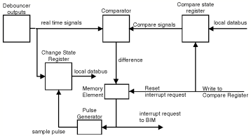
Figure 4-2 Change of State Circuit
To detect a change in the input lines the pattern comparator must compare the "Real Time" input lines with a copy of the old state of the input lines. Thus a copy should be made of the present state of the input lines, by reading the Current State Register, and this data should be written into the Compare State Register.
Writing to this Compare State Register resets the memory element to a "no-interrupt" status. The output of the comparator should now be inactive (no differences). The output of the comparator will go active (a difference) as soon as one or more of the inputs change their level. The memory element is set to the "interrupt" status and asserts the interrupt request line to the BIM. Also the sample pulse generator is triggered and a sample of the outputs of the debouncer is stored in the Change State Register. Data read from this Change State Register will now reflect the state of the input lines when the change was detected.
![]()
[Next]
[Previous] [Up] [Top] [Contents] [Back]
![]()