[Next]
[Previous] [Up] [Top] [Contents] [Back]3.2 Group Description
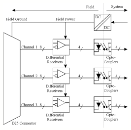
Figure 3-2
shows a function diagram of the input circuit for each Group on the CC133. 
Figure 3-2 Group Input Circuit
The input signals are passed via a D25 male connector to the CC133. Each D25 connector receives the signals for three channels. The differential input signals are converted to standard TTL signals using differential receivers. The differential receivers meet the requirements of the RS-422-A standard. Each group of differential receivers is powered by a separate DC/DC converter.
The 'minus' inputs can be set to 1.6Volt, to let the 'plus' inputs accept TTL level single ended input signals.
Opto-couplers are used for galvanic isolation between the differential receivers and the system.
![]()
[Next]
[Previous] [Up] [Top] [Contents] [Back]
![]()