[Next]
[Previous] [Up] [Top] [Contents] [Back]3.2 Group Description
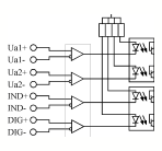
Each channel of the CC133 consists of four signals: two Quadrature signals, one Index signal and one Digital Input signal.

Figure 3-3 Channel Input Circuit
The Quadrature signals are used to supply information from the field to the control system. The information is translated by the encoder circuits into numeric values. The logic levels of the Quadrature signals and their relative edges will result in an increment or decrement function of the encoder counters, depending on the current operating mode of the encoder circuits.
The Index signal can be used to reset the encoder counters and generate an interrupt to the VMEbus. The Digital Input signal can serve several functions within the working environment, and can also be used to generate an interrupt to the VMEbus. The interrupt capability of both signals is fully described in the next section.
![]()
[Next]
[Previous] [Up] [Top] [Contents] [Back]
![]()