[Next]
[Previous] [Up] [Top] [Contents] [Back]4.3 Jumper Settings
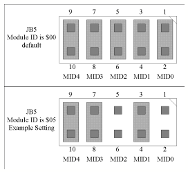
The Module ID can be set in two ways: by using the VMEbus P2 connector signals or by using the JB5 Module ID jumper block.
The Module ID signal lines MID4 to MID0 are held in a high (1) level by pull-up resistors. These signal lines can be asserted to a low (0) level by either inserting jumpers on the JB5 jumper block or by connecting the MID4 to MID0 signals to ground on the VMEbus J2 backplane.
When the VMEbus P2 signal option is used then all jumpers on JB5 must be removed. The VMEbus option allows for a geographical addressing of the module. That means that the slot position of the module defines the VMEbus address of the module. This will prevent address conflicts when using multiple CC175 modules in one system. See the VMEbus P2 connector assignments for the MID4 to MID0 signal pins.
When the JB5 jumper block is used then insert jumpers on the MID4 to MID0 signals to assert them to a low (0) level. In this case the VMEbus P2 signals must be left unconnected.

Figure 4-5 Module ID Select
![]()
[Next]
[Previous] [Up] [Top] [Contents] [Back]
![]()